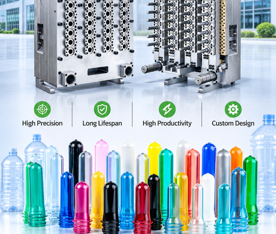
Introduction: Two Molds, One Integrated Packaging Line
For beverage bottlers, the injection molds that produce PET preforms and plastic caps are often treated as interchangeable “tooling purchases.” They are not. A preform mold and a cap mold operate under fundamentally different engineering priorities, thermal profiles, steel selections, and quality tolerances. A bottler who understands these differences makes smarter procurement decisions, avoids hidden compatibility costs, and achieves stable line performance from the injection press through to the capping machine.
At Berni Mould, we build both PET preform molds and cap molds as a unified system—not as isolated tools. This article breaks down the technical distinctions that matter most, from cavitation strategy to cycle time physics and neck-finish coordination.
1. Core Engineering Priorities: Precision vs. Velocity
The most consequential difference lies in what each mold is optimized to deliver.
A PET preform mold is engineered around weight consistency and concentricity. A preform is a thick-walled, high-aspect-ratio tube that must later be reheated and stretch-blown into a bottle. If the preform’s wall thickness varies by even a fraction of a millimeter, the blow molding process produces uneven material distribution, weak spots, and scrap. Every cavity must deliver identical gram weight and dimensional stability under high injection pressure. This demands perfect cavity alignment, advanced cooling circuit design, and corrosion-resistant steels such as S136 for sustained contact with PET melt.
A cap mold, by contrast, is engineered around cycle time and ejection efficiency. Beverage caps are thin-walled, high-volume parts produced in seconds. The mold must fill, cool, open, and eject a complete shot with minimal delay. Modern cap cells achieve cycle times in the 5–8 second range, with strip-plate systems, unscrewing mechanisms for threaded closures, and hot runner systems optimized for uniform filling across 24 to 128 cavities. The engineering focus is on thermal uniformity in thin sections and reliable ejection without deformation.
2. Hot Runner Architecture: Valve Gate Dominance in Preforms
The runner system represents one of the clearest technical divides between the two mold types.
Multi-cavity preform molds almost universally employ valve-gated hot runner systems. Each cavity has its own heating zone and thermocouple, and the valve gate closes positively at the end of injection. This eliminates the sprue at the preform base, ensures a consistent amorphous gate point, and prevents runner blockage during interruptions. The cost is significant—valve-gated hot runners can run upward of $2,500 per cavity—but the payoff is weight consistency and minimized acetaldehyde (AA) generation. For high-cavitation preform tools, especially those running carbonated beverage applications where AA content is critical, valve gating is non-negotiable.
Cap molds also use hot runners, but the thermal challenge is different. Because cap walls are thin, the melt must fill the cavity rapidly before freezing occurs. Hot runner balance is critical, but the gate design often prioritizes shear control and cosmetic appearance on the cap top or interior. Unscrewing molds for threaded caps add another layer of complexity: the core must rotate out of the thread without damaging the delicate tamper-evident band geometry.
3. Cooling: The Dominant Variable in Preform Cycle Time
In preform molding, cooling time dominates the cycle. The thick wall of a preform—often 2.5 to 4 mm for standard beverage applications—stores substantial heat that must be removed before ejection. The relationship follows a roughly squared function:
A 3 mm wall preform requires approximately 10.8 seconds of cooling; an 8 mm wall preform for a 5-gallon water bottle requires nearly 77 seconds.
This physics dictates preform mold design. Cooling channels must be positioned aggressively close to the cavity and core surfaces, and post-mold cooling robots are often employed to continue cooling the preform outside the mold while the next shot is injected. Independent water circuits for the cavity, core, neck insert, and gate area allow fine-tuned thermal management. Any imbalance in cooling across cavities produces dimensional drift that propagates downstream to the blow molder.
Cap molds, with their thin walls, cool much faster. The challenge is not total heat removal but uniformity across high cavitation. A cap that cools unevenly may warp, seal improperly, or fail tamper-evident band integrity. Cap mold cooling design prioritizes turbulent flow through small-diameter channels in the cavity and core inserts, often with separate circuits for the top, sidewall, and thread region.
4. Steel Selection and Wear Modes
Both mold types face abrasive and corrosive environments, but the wear mechanisms differ.
Preform molds encounter high-pressure PET melt at temperatures exceeding 280°C. The core and cavity surfaces must resist corrosion from PET degradation byproducts and maintain polished surfaces that release the part cleanly. Swedish Stavax ESR (S136) is a common choice for cavity, core, and neck inserts, offering corrosion resistance and polishability. Mold bases frequently use P20 with nickel plating or stainless steel for durability.
Cap molds experience high-speed mechanical wear from ejection and unscrewing mechanisms. Thread cores and stripper rings slide against each other thousands of times per shift. H13 or 1.2767 steel is often specified for wear resistance in these moving components, while food-contact surfaces require stainless grades. Galling resistance in the stripper ring/core interface is a persistent design concern; tapered mating surfaces and precise clearances prevent the seizing that can halt production.
5. The Neck Finish: Where the Two Molds Must Agree
Perhaps the most overlooked engineering interface is the neck finish. The preform mold forms the neck geometry—threads, tamper-evident bead, and sealing surface—in their final crystallized state. The cap mold forms the closure that must mate with that exact geometry. If the two molds are not designed to the same dimensional standard, the consequences range from excessive opening torque to seal failure and leakage.
For carbonated soft drink lines, PCO 1881 is the dominant neck finish specification. The preform neck insert must hold the neck dimensions within tight tolerance while achieving the correct crystallinity through controlled cooling. The cap mold’s core and cavity must produce a closure whose thread engagement, tamper band bridges, and sealing liner (or linerless seal) match that neck precisely. At Berni Mould, we design preform and cap molds as matched pairs when both are supplied to the same bottler, ensuring that the neck finish reference geometry, tolerances, and cooling-induced shrinkage are coordinated from the start.
6. Cavitation Strategy: Matching the Line, Not Just the Machine
Cavitation decisions for preform and cap molds should be driven by the filling line’s throughput requirements, not by the maximum shot capacity of the injection press alone.
Preform molds for mid-market beverage operations commonly run 48, 72, or 96 cavities, while high-speed plants may specify 144 or higher. The limiting factor is often plasticizing capacity: the injection unit must melt and inject the required shot weight within the cooling time. If plasticizing cannot keep pace, added cavities sit idle.
Cap molds typically run 24 to 128 cavities, with cycle times measured in seconds rather than tens of seconds. The downstream equipment—slitting and folding for tamper bands, vision inspection, bagging—must match the cap cell’s output. A 96-cavity preform mold feeding a blow molder that produces bottles at 40,000 per hour requires a cap mold and downstream system sized to deliver closures at that same rate. Misalignment here creates inventory imbalance or line starvation.
7. Quality Control: Different Metrics, Same Consequence
Preform quality control centers on dimensional and weight consistency: gram weight per cavity, neck ID/OD, body wall thickness distribution, and AA content. A preform that passes these checks will blow reliably.
Cap quality control centers on functional performance: removal torque, application torque, tamper band integrity, seal compression, and top-load strength. A cap that passes these checks will run through the capper and protect the product.
Yet both sets of metrics feed the same outcome: line efficiency and package integrity. A preform with a slightly oval neck will produce a bottle that leaks despite a perfect cap. A cap with a weak tamper band will fail in the capper despite a perfect preform. This is why Berni Mould treats the neck finish as a shared critical interface and validates preform and cap tooling together whenever both are within our scope.
8. Why a Single-Source Approach Reduces Risk
Bottlers who source preform molds and cap molds from separate suppliers often discover hidden compatibility costs during commissioning. The preform neck may be within its own tolerance but outside the cap’s acceptance window. Cooling-induced shrinkage may shift dimensions in ways neither supplier modeled independently.
A mold supplier who builds both tool types can coordinate design parameters from the outset: identical neck finish reference geometry, matched thermal shrinkage allowances, compatible steel selections for wear pairs, and consistent documentation. When troubleshooting is needed, there is one technical team accountable for the entire injection side of the packaging line—not a blame exchange between two vendors.
Comparison at a Glance
| Design Variable | PET Preform Mold | Cap Mold |
|---|---|---|
| Primary objective | Weight consistency, concentricity, AA control | Cycle speed, ejection reliability, thin-wall uniformity |
| Hot runner | Valve-gated, per-cavity thermal control | Hot runner with shear-controlled gating; unscrewing or strip-plate ejection |
| Cooling challenge | Thick-wall heat removal; t² relationship dominates cycle | Uniform thin-wall cooling across high cavitation |
| Typical steel | S136 / Stavax ESR for cavity, core, neck insert | H13, 1.2767 for wear parts; stainless for food contact |
| Typical cavitation | 48–144+ | 24–128 |
| Critical interface | Neck finish (e.g., PCO 1881) — must be matched between both molds | |
| Key QC metrics | Gram weight, neck ID/OD, wall thickness, AA | Torque, tamper band integrity, seal, top-load |
Conclusion: Know the Difference, Specify Accordingly
PET preform molds and cap molds are not interchangeable tooling categories. One prioritizes weight consistency, cooling physics, and valve-gated melt delivery. The other prioritizes cycle speed, ejection reliability, and thin-wall thermal uniformity. The bottler who understands these distinctions writes better specifications, asks sharper questions during procurement, and avoids the costly surprises that emerge when mismatched molds meet on the production floor.
At Berni Mould, we design and manufacture both PET preform molds and cap molds with the interface—the neck finish—as the anchor of the system. Whether you are running a 48-cavity preform tool and a 64-cavity cap tool for a water line, or a high-output valve-gated system for carbonated beverages, the engineering decisions should be made together.