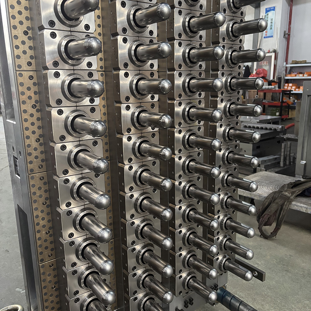
Preform warping and deformation remain among the most persistent quality defects in PET injection molding. While material selection, injection pressure, and holding profiles all influence final part quality, the single most decisive factor governing dimensional stability is the thermal history the preform experiences inside the mold. Specifically, the layout of the cooling circuit determines whether every gram of PET solidifies under uniform, controlled conditions—or under thermal gradients that lock residual stress into the part before it ever reaches the blow molding stage.
At Berni Mould, we design and manufacture PET preform molds and bottle cap molds for converters who cannot afford to tolerate deformation-related scrap. This analysis examines the mechanisms linking cooling circuit design to preform warp, and the engineering principles we apply to eliminate it at the source.
1. Why Preforms Warp: The Thermal Gradient Mechanism
PET is a semi-crystalline polymer with a glass transition temperature around 78°C and a melting range of 245–260°C. When molten PET enters the injection cavity, it begins to cool from the cavity wall inward. If the cooling rate varies across the preform’s circumference, wall thickness, or length, different regions of the part reach their solidification point at different times. The regions that solidify first become rigid while adjacent regions are still shrinking—and that differential shrinkage translates directly into warp, ovality, or bending.
The critical variable is not cooling speed but cooling uniformity. A circuit that removes heat aggressively from one side of the cavity while starving another creates exactly the conditions for deformation. Research on PET preform thermal behavior confirms that the body wall should be held within a narrow temperature band during cooling to avoid stress gradients that persist through subsequent processing [citation:1][citation:4].
2. The Anatomy of an Optimal Cooling Circuit Layout
A cooling circuit that prevents deformation must satisfy three conditions simultaneously: proximity, balance, and zone isolation. Traditional straight-drilled channels often fail on at least one of these.
2.1 Proximity Without Sacrificing Mold Strength
The distance between the cooling channel wall and the molding surface directly governs heat transfer rate. Patent literature on preform mold inserts specifies minimum distances in the range of 0.8 mm to 5 mm between curved cooling stretches and the molding surface, depending on the specific preform geometry and insert design [citation:2]. Closer is generally more effective—but too close risks stress concentration in the mold steel and premature fatigue.
Berni Mould addresses this by using conformal cooling geometries in critical zones rather than uniform offset drilling. The neck finish area, the support ring transition, and the gate region each present different thermal loads. A circuit that maintains constant offset from a complex surface will inevitably under-cool some features and over-cool others.
2.2 Thermal Balance Across the Circumference
Preform ovality—where the cross-section deviates from circular—is the signature defect of circumferentially imbalanced cooling. This occurs when inlet and outlet channels are arranged such that one side of the cavity sees coolant at a significantly lower temperature than the opposite side. In a multi-cavity mold, the problem compounds: cavities at the end of a series circuit receive warmer coolant than cavities near the inlet.
Independent research on multi-cavity PET preform molds demonstrates that parallel, independent cooling circuits per cavity (or per small cavity group) reduce inter-cavity temperature variation to within ±1°C, compared to 20–25% efficiency loss in series configurations [citation:15]. For a 48-cavity or 72-cavity mold, this difference directly determines whether all preforms in a production lot share the same shrinkage characteristics.
2.3 Zone-Specific Temperature Control
Not every region of a preform should be cooled at the same rate. The gate area is the last to fill and carries the highest thermal load. The neck finish, which must remain dimensionally precise for closure compatibility, requires rapid and uniform cooling. The body wall, which will undergo biaxial orientation during blow molding, should cool at a rate that preserves a consistent amorphous structure.
Optimal circuits therefore use independent loops for the core, cavity, neck insert, and gate areas. A 2025 study on lightweight preform molds confirmed that dedicated cooling channels for internal and external surfaces, combined with zone-specific temperature control, improved temperature distribution and reduced cycle time while maintaining dimensional accuracy [citation:5].
3. Circuit Geometry: Where Layout Decisions Are Made
The difference between a warping preform and a stable preform often comes down to the geometry of the coolant path at specific locations.
3.1 The Neck Finish Zone
The neck finish has the tightest dimensional tolerances of any preform feature because it must accept a closure without leakage. Cooling here must be rapid but exceptionally uniform. A circuit that approaches the neck from one direction only—common in simplified mold designs—will produce measurable ovality. Optimal layouts use annular or spiral channel segments that surround the neck insert symmetrically, ensuring equal heat extraction at every angular position.
3.2 The Support Ring and Transition Zone
The transition from the thick support ring to the thinner body wall is a classic hot spot. Thick sections cool more slowly and shrink more than adjacent thin sections, creating a bending moment as the part solidifies. Patent designs specifically address this with curved cooling stretches positioned at controlled distances from the support ring groove and the tapered flange [citation:2]. Berni Mould incorporates dedicated circuit segments that target this transition directly, rather than relying on conduction from channels positioned for the body wall.
3.3 The Core Side: Often Neglected
Much attention focuses on the cavity side of preform molds, but the core (internal) surface removes heat from the inside of the preform. If core cooling is less effective than cavity cooling, the preform solidifies from outside inward in a way that leaves the inner surface under stress. Optimal layouts treat core cooling as an equal partner: independent internal circuit loops, often with a dedicated temperature control unit, ensure that the through-wall thermal gradient is symmetric.
4. Flow Dynamics: Why Circuit Path Matters as Much as Circuit Position
A cooling channel that is correctly positioned but poorly flowed will not perform as designed. Two flow characteristics determine effectiveness:
- Turbulence: Coolant must be in turbulent flow (Reynolds number above approximately 4,000) to maximize convective heat transfer. Laminar flow effectively insulates the channel wall from the bulk coolant. Circuit layouts that use excessive series length, small diameters, or excessive bends can drop the flow rate below the turbulence threshold in downstream sections.
- Absence of dead zones: Sharp corners, sudden expansions, and poorly joined channel segments create stagnant regions where coolant does not exchange heat effectively. Advanced mold manufacturing techniques—including the use of smoothly connected circular or elliptical channel sections without edge discontinuities—eliminate these stagnation points [citation:2].
Berni Mould specifies channel diameters and circuit lengths for each mold based on the required flow rate and pressure drop, ensuring that every cavity receives coolant in the turbulent regime with a consistent flow distribution.
5. Simulation-Driven Layout Validation
A cooling circuit layout that appears correct on a drawing can still produce warped preforms if it is not validated against the actual thermal load of the specific preform design. Modern mold engineering relies on computational fluid dynamics (CFD) and thermal simulation to predict:
- Temperature distribution across the molding surface at ejection
- Differential shrinkage vectors that indicate warp potential
- Hot spots where cooling capacity is insufficient for the local heat load
- Flow imbalance in multi-cavity configurations
For complex preform geometries—particularly lightweight designs with aggressive wall thickness reduction—simulation is not optional. A 2025 study on lightweight preforms showed that structural and thermal simulations were essential to achieving the target bottle shape under reduced pressure while maintaining dimensional stability [citation:5]. At Berni Mould, we run thermal validation on every new preform mold design before cutting steel, identifying and correcting potential warp-inducing temperature gradients in the virtual stage rather than the trial stage.
6. The Production Consequence: What Optimal Layout Delivers
The measurable outcomes of a properly engineered cooling circuit extend beyond the absence of visible warp. Processors working with Berni Mould preform molds typically observe:
- Reduced dimensional variation: Cavity-to-cavity and lot-to-lot consistency in critical dimensions, including neck ID/OD and body wall thickness distribution.
- Lower residual stress: Preforms that do not carry locked-in stress from the injection stage blow more predictably, with fewer blow-out failures and more uniform wall distribution in the final bottle.
- Shorter cycle times without quality trade-offs: Uniform cooling reaches the ejection temperature faster than uneven cooling, because no region is holding the part in the mold while waiting for a slow-cooling zone to catch up.
- Reduced scrap and rework: Deformation-related rejects—ovality, bending, and gate-area distortion—are eliminated at the source.
For bottle cap molds, the same principles apply with even tighter tolerances. A cap that is out of round by even a few hundredths of a millimeter will leak or fail to seal. The cooling circuit layout in a high-cavity cap mold must deliver identical thermal conditions to every cavity, every cycle.
Engineering Preform Molds Where Cooling Is Not an Afterthought
Berni Mould designs and manufactures PET preform molds and closure molds with cooling circuit layouts engineered for dimensional stability from the first shot. If you are experiencing deformation-related scrap or inconsistent preform quality, our engineering team can review your cooling requirements and propose a layout optimized for your specific preform design and production conditions.
Keywords: PET preform mold manufacturer, bottle cap mold supplier, preform cooling circuit design, prevent preform deformation, conformal cooling PET mold, Berni Mould
7. Summary of Design Rules for Deformation-Free Cooling
- Design for uniform heat extraction, not maximum heat extraction. The goal is equal cooling rate across all surfaces that must maintain dimensional relationships.
- Isolate zones. Neck, body, gate, and core require independent circuit control.
- Parallel, not series, for multi-cavity. Every cavity should see coolant at the same temperature and flow rate.
- Maintain turbulence. Size channels and circuits so that Reynolds number stays above 4,000 throughout the path.
- Eliminate dead zones. Smooth transitions and continuous channel geometry prevent stagnant coolant and localized hot spots.
- Validate with simulation. Thermal and flow analysis before steel cutting identifies warp risk that visual inspection cannot.
- Treat core cooling as equal to cavity cooling. Through-wall symmetry is as important as circumferential symmetry.
Preform warp is not an inevitable cost of high-speed injection molding. It is a predictable outcome of thermal imbalance—and thermal imbalance is a design choice. At Berni Mould, we choose layouts that eliminate it.